Preliminaries
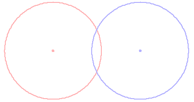
Click this image to add a right triangle
This page examines some of the mathematical properties of lenses and the conventions used by lens designers, with particular emphasis on OpticalRayTracer.
First, as explained in the OpticalRayTracer help file, the most basic way to think of a simple spherical lens is as
two overlapping circles. See the graphic to the right, and click it to add a useful right triangle, one that allows us to begin shaping the mathematical relationship between these circles and a simple lens.
In this graphic, we see that:
sr = the radius of the virtual sphere that defines one surface of the lens.
lr = the lens radius, the distance from the center of the lens to one edge.
d = the distance between the center of the lens and one surface.
a = the base of the right triangle formed by sides a/lr/sr.
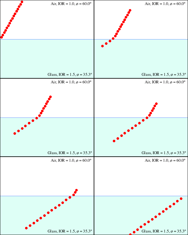
Click this image to repeat the animation
This triangle is useful for sorting out the relationship between these virtual circles/spheres and our lens. On examination, it can be seen that:
|
(1)
|

|
|
(2)
|

|
And therefore:
|
(3)
|

|
|
(4)
|

|
These equations can be used to produce a lens with specific traits. But is is important to remember that the above equation set assumes a symetrical lens, a lens with both radii the same. For a lens with different radii on each side, one can simply increase the number of equation terms — two sphere radii, most importantly.
Refraction
To apply these equations to the optical behavior of a lens, we must discuss refraction. Refraction is a property of some materials in which light travels more slowly than in air. In typical glass, for example, light travels about 33% more slowly than it does in air.
This speed differential produces an interesting effect. To see the effect, click the second graphic on this page and watch the animation. Notice the row of photons approach the border between air and glass. Notice that the photons that arrive first are slowed down in advance of their siblings farther to the right. This causes the row of photons to change its direction of travel. If you think of the row of photons as a wavefront (the other, equally valid, interpretation of photon behavior), you will realize that the speed difference between air and glass has caused the wavefront to change direction.
It is not an oversimplification to say that all of lens design is primarily meant to exploit this single property of glass. By selectively slowing light down, we can cause a wavefront to converge or diverge, or change direction for some other reason, as in the example of a prism.
It is important to add that, in a basic physical sense, light's speed is a constant, and the optical effect being discussed doesn't cause light to actually change its speed. It is more accurate to say that glass makes light take a longer journey at its normal speed.
Each optical material has a particular
Index Of Refraction (IOR), which is the ratio of the speed of light in the material to its speed in a vacuum. The IOR of typical glass is about 1.5, which means light travels at a speed of
c/1.5 in glass,
c being the speed of light in a vacuum.
The highest IOR for readily available glass is about 1.75 for certain flint glasses, but diamond has an IOR of about 2.42.
Click here to visit a site with a list of materials and their indices of refraction.
Snell's Law
The relationship between the indices of refraction of various materials and the resulting angular refraction is expressed in
Snell's Law:
|
(5)
|

|
Where:
n1 = index of refraction of material 1.
θ1 = angle of incidence in material 1.
n2 = index of refraction of material 2.
θ2 = angle of refraction in material 2.
Note that, for the indices of refraction denoted by n
1 and n
2 above:
|
(6)
|

|
To say it with words, an index of refraction
n is defined as
c/v, the ratio of the speed of light in a vacuum divided by the speed of light in the material in question.
A practical rearrangement of the Snell's Law equation, with which we may obtain refraction angles, is:
|
(7)
|

|
Note that this equation, like the Snell's Law equation from which it is derived, is pleasantly symmetrical. It makes no assumptions about the two indices of refraction n
1 and n
2. This property is useful to remember when considering the case of a light wavefront moving from glass to air, where the relationship between n
1 and n
2 is reversed.
By examining the Snell's Law equation, one can see that, in the case where n
2 > n
1, the angle of refraction is less than the angle of incidence. It is also apparent that an angle of incidence of 0 will always result in an angle of refraction of 0, meaning perpendicular rays are not refracted.
Here is a practical problem using equation (7) where n
1 = 1.0, n
2 = 1.5, and a
1 = 60°:
|
(8)
|

|
Focal Length
Turning now to a more practical aspect of lens design, we can use the chosen properties of a lens to determine its focal length. But it is important to emphasize that, unlike the equations shown above,
straightforward focal length computations are always approximate, which is why ray tracing is a necessary step in any meaningful lens design. Here is what is commonly known as the "Lensmaker's Equation," with the caveat that it only produces reasonable results for relatively thin lenses:
|
(9)
|

|
Where:
f = lens focal length.
r1 = sphere radius for one side of the lens.
r2 = sphere radius for the other side of the lens.
On first examining this equation, the reader may think something is in error, since the two lens radii are subtracted from each other, which would produce zero for a symmetrical lens. But the two radii values are treated using the "Cartesian sign convention," which proceeds as follows:
- Light rays are assumed to travel from left to right (the convention adopted in OpticalRayTracer).
- The light source is assumed to be a point or plane (both provided in OpticalRayTracer), located to the left of the first lens.
- The radius of a virtual sphere centered in front of the lens (toward the light source) is given a negative sign.
- The radius of a virtual sphere centered behind the lens (away from the light source) is given a positive sign.
Application of this rule to the first graphic image on this page would mean that the radius of the red sphere, located in front of the lens, would be given a negative sign.
There is this simplified form of the Lensmaker's Equation, used for symmetrical lenses, lenses whose left and right radii are equal:
|
(10)
|

|
Let's test the usefulness of this equation using OpticalRayTracer. Run OpticalRayTracer and enter the following values:
In the "Configuration" tab:
- Number of Tracing Beams = 2
- Diverging Beam Source = not selected
Now create a lens with these traits:
- Symmetrical = selected
- Lens radius = 2 (the default)
- IOR = 1.52 (the default)
- X position = 0
- Y position = 0
- Left Sphere radius = 12 (applies to both radii)
Remove any other lenses from the beam path and see where the two tracing beams converge, which is the location of the focal point of the lens for the chosen conditions.
For a symmetrical lens with two radii of 12 and an IOR of 1.52 and applying equation (10), we should expect to see:
|
(11)
|

|
In examining the actual focal point in OpticalRayTracer, we see it lies at about 11.23, an error of about 3%. If we now increase the number of tracing beams to the default of 6, we see that the various beams do not converge at a single point. This deviation from perfect focus is called "spherical aberration," it is a trait of all lenses that have a spherical cross-section, and it is more severe for lenses with a short focal length.
By experimenting with OpticalRayTracer in its present setup, the reader can establish that the lens is better-behaved when its focal length is comparatively large, but there is always some significant deviation from the outcome predicted by the Lensmaker's Equation.
Hyperboloid Lenses
Along with the common spherical lens, OpticalRayTracer models another kind of lens, one with much better performance than the spherical, but one that is much more difficult to fabricate in glass.
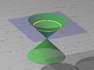
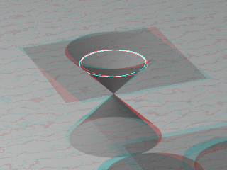
When modeling a spherical lens, one need only specify one radius per sphere, as shown in the first graphic on this page. But when modeling a hyperboloidal curve, things are not so simple. Those properly trained in math will recall that circles, ellipses, parabolas and hyperbolas are all conic sections, or slices through a cone.
Examine the two graphic images to the right on this page. Click the top image repeatedly to cycle through the conic section images for a circle, ellipse, parabola and hyperbola. If you have a pair of anaglyphic eyeglasses (recommended), put them on and click the lower image in the same way for 3D views of the conic sections.
OpticalRayTracer relies on various derivative forms of the following equation to create/model hyperboloid lenses:
|
(12)
|

|
Where:
y = Vertical coordinate for a given x argument.
r = Lens sphere radius.
d = Lens depth, as above.
cf = Curvature factor, a lens shape fine-tuning prameter.
In OpticalRayTracer, the curvature factor has a meaningful range of 0 <= cf <= 0.25.
Equation (12), despite its central importance to the computations carried out, doesn't appear in the displayed form in OpticalRayTracer. It is instead the basis for a rather complex hyperboloid-line intersection routine used to process light paths during ray tracing.
Equation (12) is also restated as equation (13) below, used in OpticalRayTracer to draw hyperbolic lens profiles in the user interface:
|
(13)
|

|
Where:
x = Horizontal coordinate for a given y argument.
r = Lens sphere radius.
d = Lens depth, as above.
cf = Curvature factor, a lens shape fine-tuning prameter.
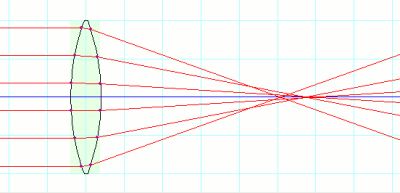
Click image to switch between spherical and hyperboloid lens
|
|
|
Here is an example lens design using the hyperboloid lens feature of OpticalRayTracer, similar to that provided in the help file. Start out with these settings:
In the "Configuration" tab:
- Number of Tracing Beams = 6 (the default)
- Diverging Beam Source = not selected
Create a lens with these traits:
- Symmetrical = selected
- Lens radius = 2 (the default)
- IOR = 1.52 (the default)
- X position = 0
- Y position = 0
- Left Sphere radius = 6 (applies to both radii)
Examine the lens focal point. The short focal length chosen for this lens produces a rather severe spherical aberration, as shown in the accompanying image. Now select "Left Hyerboloid," which, because you have enabled the "symmetrical" mode, will change both lens surfaces at once.
Now enter 0.074 for "Left Curv. Fact.". This will optimize the lens for this focal length and almost completely eliminate the spherical aberration that was evident before. Those who are following along without running OpticalRayTracer should click the accompanying graphic to see the change.
Conclusion
In reading this article and hopefully while carrying out some of the exercises, I think the reader will realize something that most people realize who work in optics — it is a science only up to a certain point, for example when performing Snell's Law computations. After that, lens design becomes very much an art form. Consider that we have created a very simple system with one symmetrical lens, but in order to make the lens focus properly we have had to depart the realm of clean, closed-form solutions in favor of ad-hoc experimentation. For example, who has the equation set that tells us that 0.074 is the correct curvature factor for a particular lens? I don't think such a thing exists.
Once a design is undertaken involving more than one lens, or with asymmetrical lenses, composed of differing glass types and indices of refraction, with the added factor of material dispersion, it quickly becomes clear that lens design is 90% art.


 Share This Page

 Share This Page




 Share This Page