

 Share This Page
| Home | | Programming Resources | | Home Automation | | | | Share This Page |
(double-click any word to see its definition)
Introduction
This section deals with what I personally regard as the most interesting part of having a home automation system — yes, that's right, the home automation part.
The ISY-26 system controller is a self-contained computer that can be programmed to control your house system, send e-mail notifications of unexpected events, activate controls according to a schedule, and it does this autonomously. After it has been configured, it no longer needs to be connected to a computer, because it is a computer.
The ISY-26 can be configured and programmed from any computer having a browser with Java installed. With appropriate security precautions, that computer can be located anywhere in the world.
Installation
We must first deal with some hardware installation issues. We'll be installing the modem (2412S) and the system controller (ISY-26) and managing its connections to your desktop computer and/or home network.
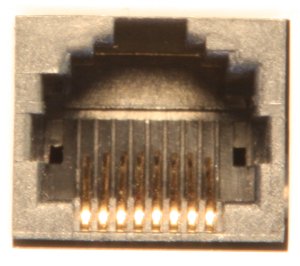
Before connecting these parts together, I ask that you closely inspect the 2412S modem, in particular the "interface cable" connection at the bottom of the unit. This is an ordinary 8-pin RJ-45 connector that very rarely causes problems for anyone, but it was the cause of a problem during my installation, and in my online research I have discovered there have been other cases of a factory problem with the connector on this modem.
When I first installed the modem and system controller, the ISY-26 system controller gave an anomalous indication (RX LED constantly lit) that I realized could mean trouble. After a few tests, I decided to examine the connections. I found that the leftmost and rightmost pins (pins 1 and 8) on the modem's RJ-45 connector were both squashed down flat into the channels meant to align them with the mating connector (see photograph this page).
I saw that I had two choices — I could return the modem and demand a replacement, or I could use a long, slender sewing needle to pry the trapped pins into their intended position. At risk of making another gratuitous editorial remark, the reader may know there is a near-perfect correlation between an American's age and his willingness to fix things himself. It seems that if an American was born before about 1960 and he wants something, he will build one or fix the one he has. After 1960, a new kind of American arrived, the kind who only ever buys something ready-made, and whines when it breaks — "fix it, daddy!". In fairness I hasten to add that I live in a house filled with things Made in China, including ... the modem under discussion.
I suggest that the reader examine the modem connector (use the photograph on this page as a guide) before installing the modem or connecting it to the system controller, and if the connector defect is present, decide how to proceed (sewing needle, ship it back, sewing needle, ship it back — all these decisions!). I suspect this is a fairly common fault, and I also suspect these modems are not tested before leaving the factory — if they were, this defect would prevent a successful test.
Once we're past this hurdle, we can install the modem and the system controller — locate the ISY-26 system controller's serial cable, the cable with a DB-9 connector on one end and an RJ-45 connector on the other. Connect the controller to your home network by way of an Ethernet cable. Connect the modem to the controller, plug the modem in, then power the controller by way of its power adaptor. I have read that one wants to power the controller up last (this may not be a real requirement, and it should become less important in newer software versions).
Initial Connection and Testing
In order for the ISY-26 to make itself visible on your home network, the latter needs to have access to a DHCP server. This is a very common property of home networks and it will probably be true for yours. In particular if you have an 802.11 wireless access point connected to your network, the DHCP requirement will most likely be met.
Another requirement for communicating with the ISY-26 is an up-to-date Java runtime engine, available as a free download here.I've decided not to try to exhaustively deal with the topic of making first contact with the ISY-26 — there are too many variations brought on by differences between operating systems. But I will offer two short summaries for Linux and Windows. Linux first, of course.
Linux:Windows:Setting the ISY-26 Debug FlagLinux:
- Run Internet Explorer
- Launch the ISY-26 Administrative Console applet (as explained above).
- Select "Tools ... Sun Java Console".
- Open a command shell and type "ControlPanel".
- In the Java Control Panel, select "Advanced ... Java Console ... Show console".
- Click "Apply".
Initial Configuration
First and very important — the ISY-26 Administrative Console is a Java applet, which means the browser window that launched it must not be closed. This is an important point to keep in mind while running this program — if you close the browser, the applet will also close.
First, choose a password other than "admin". Select "File ... Set Userid/Password" and make your entries.
Next, set a geographical location. This is important for computing sunrise and sunset times. Select the "Configuration" tab, then click "Change Location". You may choose a city from the provided list (it's not necessary to exactly match your geographical position), or you may directly enter your latitude, longitude and time zone offset (to get the latitude and longitude for most ZIP codes, click here, enter your state and city and take note of the latitude and longitude). For the latter options, you may have to use the mouse cursor to stretch the location dialog horizontally, to bring the longitude entry into view.
When you are done setting your location, click "Synchronize the Clock with Computer's Time." In most cases this will provide the ISY-26 with a suitable clock and time zone setting. In a future software version, the ISY-26 will synchronize itself automatically and periodically, assuring a very high accuracy for timed events, but at the time of writing this feature isn't enabled.
NOTE: If the above statement is out of date and the ISY-26 should be able to set its own clock but isn't doing so, go back to the step above where you set a static IP address, and make sure you have entered a valid DNS name server address. Without a DNS address, the ISY-26 won't be able to set its clock.
Adding Insteon Controllers to the ISY-26
Now the fun begins — you're going to tell the ISY-26 about the controls you've installed. There are lots of ways to do this, but the fastest and most reliable way is to write down the address of each Insteon control as you install it, then enter that address into the ISY-26 console. Here's how to enter an address:
If the search is successful, a new item will appear under "Devices" with the entered address as its name. You can and should rename it with something more useful to you, like its location.
Repeat this procedure for all the Insteon controls you have installed.
To test the ability of the ISY-26 to communicate with the installed controls, right-click "Devices" and choose "Query". The ISY-26 will scan the installed devices to establish their present state (whether on or off and their identity). This scan may take some time.
Making Scenes
I personally think calling this feature "Scenes" was a mistake (and someday I am going to make a scene about it). The name "Scenes" will only confuse people — it should have been called "Groups". So, to avoid mental anguish, cognitive dissonance and psychic tsunamis, I suggest that my readers mentally translate "Scenes" into "Groups".
You may remember during the installation phase, we had a discussion about paired controls, for example controls located on a staircase, each of which must be able to control all the lights. You may recall that, because of the cleverness of Insteon controls, it's not necessary to physically wire all the lights, or all the controls, together to achieve this. The new way to do this is to programmatically group the controls, so they talk to each other across the house wiring.
On the installation page I discussed creating groups by directly clicking on control buttons, but this is a very inefficient way to do this, and it sometimes creates unintended results unless everything is done just so. The ISY-26 console can create groups much more efficiently, and it will diagram them as well, so there is no ambiguity about how the system is set up.
Let's say for this example that you have two controls, one at each end of a staircase, and you want them both to control the staircase lights in the same way. Let's arbitrarily call the controls "Up" and "Down". You can actually name your controls this way if it helps to follow the process.
It's important to note that the controller behavior of a control is only valid if the control is manually activated. If you turn on a control from the ISY-26 console program, the other members of that control's group will not be activated. But if you turn on a light using that control's switch, all the grouped controls will be activated.
If you change your mind about the behavior of a control that is part of a group, if you want to switch it to controller from responder or vice versa, you need to remove the control from the group and re-insert it. At the time of writing there is no way to change the behavior of a control once it has been placed in a group. I suspect this will also change as the software improves.
Orphan Controls
In a typical setup, the majority of controls become part of a scene, and because of this, manual activation events are broadcast across your home network (this is how one control activates another). The ISY-26 controller picks up the broadcasts, and its displays and event log accurately represent the state of your system.
But if you manually activate a control that is not part of a scene, it won't report its new state across the network, and the ISY-26 won't know the control has been activated. If you don't need to know the exact state of your home network, this won't matter. But if you want the ISY-26 controller displays and Web pages to accurately reflect the state of all your controls, take these steps:
Creating scenes with a single member may seem odd, but once this is done, the control will broadcast its state when it is activated, and the ISY-26 will know the exact state of your network.
The basic idea is that the ISY-26 monitors and keeps track of all controls that are part of scenes (and that are activated as scenes), but controls that are not part of scenes don't broadcast their state when they are manually activated. So if you want to maintain an accurate picture of the state of your network, make all controls members of scenes, even if you must create scenes having only one member.
Programming an Insteon Remote Control
Insteon remote controls have it all over their X-10 predecessors, and if only they had more buttons, I would regard them as ideal. But as to making a remote like the 2440BK work with the ISY-26 controller, this is very easy and much simpler than the manual programming method described earlier. Here are the steps:
Programming and Events
Now that the ISY-26 has been programmed with information about controls and groups of controls, we can move on to creating programs meant to detect and trigger events. Using the ISY-26 event programming features, one can turn lights on and off at specific times of day, or sense anomalous conditions and act on them by activating equipment and sending e-mails or pager alerts.
It's important to understand that the ISY-26 has quite a lot of information at its disposal — it knows the date and time of day, it knows the time of sunrise and sunset for any date (assuming you have provided your location), it knows which controls have been activated, and it knows the logical outcome of running any of its own programs. Any of these sources can be used to trigger an action.
Because of the power and complexity of the ISY-26 programming features, I won't try to describe them exhaustively — to do so would amount to a full course in computer programming. Instead I'll provide a few simple examples.
Run the ISY-26 Administrative Console as shown above and click the "Program Details" tab. Let's create a simple example program to turn on a light.Experiment with the programming features. In a more realistic situation, one might choose a time interval by using the "From" and "To" operators, and turn on one or more lights during the specified time interval and turn them off any other time. Such a program might look like this:
If
        From    Sunset  + 30 minutes
        To      Sunset  +  1 hour  and 30 minutes (same day)

Then
        Set 'External/Foyer 1' On
        Set 'External/Foyer 2' On

Else
        Set 'External/Foyer 1' Off
        Set 'External/Foyer 2' Off
Notice the actions under "Else". At first, one might assume that the "Then" specification is sufficient to turn off the chosen lights after the specified time interval, but the "Off" action is separate and must be specified, it can't be assumed. Just remember how literal computers are — you need to tell them exactly what you mean.
Here's a an example program that detects an unexpected event:
If
        Status 'WaterSensor 1' is On
     Or Status 'WaterSensor 2' is On

Then
        Set 'Water Pump 1' On
        Set 'Water Pump 2' On
        Send Notification to All

Else
        Set 'Water Pump 1' Off
        Set 'Water Pump 2' Off
This program shows one of the more advanced features of the ISY-26 — it can notify a list of recipients on detection of a specified event. I feel obliged to add that at the time of writing there is no Insteon water sensor, or for that matter, an Insteon motion sensor. But X-10 sensors exist and they can be easily integrated into an Insteon network, either by way of the ISY-26 X-10 translation capability (the topic of the next page in this article) or through the use of a gateway device like the 31275K that translates various sensor outputs into an Insteon-compatible form.
Extending the Remote Control
We return now to the issue of the 2440BK remote control's inability to shut down any scenes or controllers that it doesn't manage with one of its buttons. I wanted to be able to completely shut down all my lights with a single button-press, but I discovered the remote control wouldn't do this for controllers not linked to one of its buttons. The following steps solve this problem.
First, rename the remote's pseudo-devices to something easier to remember. Initially the pseudo-devices are named with the remote's base Insteon address plus a number between 1 and 6, example "0A.1F.DF.1". Rename each of the remote's pseudo-devices something simple like "remote_1" through "remote_6". But keep the same index numbers in the same order — this associates the devices with the buttons on the remote.
Next, create this program for "all lights off":
If
        Control 'Remote_1' is switched Fast Off

Then
        Set Scene 'Devices' Off

Else
   ...
And this one, for "all lights on":
If
        Control 'Remote_1' is switched Fast On

Then
        Set Scene 'Devices' On

Else
   ...
These programs detect the pressing of the "All Off" and "All On" remote buttons and extend their effect to all the controllers in your Insteon network, thus getting around the remote's limitation.
A Little Detail
There are some things about the program editor that won't be obvious right away. One is that you can enable or disable a program using the checkbox at the right marked "Enabled". Another is the role of the button marked "Update".
The "Update" button replaces the highlighted line with any changes the user wishes to make. This means it isn't necessary to add and delete lines to effect a small change. Instead, select a particular line at the upper right, make changes using the controls at the lower right, then click "Update" to enable the change.
Notifications
Recipients for notifications are set up by clicking the "Configuration" tab and choosing one or more items in the "Messaging Providers" list. To me, the obvious choice is the very first in the list — "Regular email". Click this choice and enter an e-mail address at the bottom of the display, where it says "Enter your full email address here". After you have entered an address, be sure to click "Add", then "Save".
By the way. This feature isn't likely to work as expected unless:Backing Up Your Work
It's always a good idea to back up your work. The ISY-26 is a complete, separate computer and the control definitions, scenes and programs listed by the Administrative Console are not stored on your computer unless you perform a backup.
Choose menu item "File ... Backup ISY", choose a suitable file location, and click "Save". This copies the current ISY-26 configuration onto the computer hosting the browser.
In the next section I will show how the ISY-26 functions as a gateway between Insteon and X-10 signals and devices.
| Home | | Programming Resources | | Home Automation | | | | Share This Page |