 Share This Page
| Home | | Computer Graphics | | Computer Aided Design | | Share This Page |
Use a computer to shape your world
— P. Lutus — Message Page —
Copyright © 2024, P. Lutus
Most recent update:
(double-click any word to see its definition)
This article is meant to provide support and resources for my CAD/CAM / SolveSpace tutorial videos which,
as they are created, will be listed here:
- Learn 3D Design with SolveSpace (released 2023.07.10)
- Learn Modern Computer Design (released 2024.04.08)
- Learn SolveSpace: Beginner to Advanced (released 2025.01.22)
Overview
This article discusses and teaches SolveSpace, an advanced, free, open-source CAD (Computer Aided Design) program. Another program named FreeCAD seems to have a wider following, but many regard FreeCAD as an inferior program because of its many unresolved bugs and steep learning curve. It's my view that SolveSpace is a better program for students, easier to learn, and the right choice for people with little exposure to CAD programs.
FreeCAD can do everything that SolveSpace can do, but has a more difficult learning curve and a number of annoying problems like its inability to create usable error messages apart from some version of "Something went wrong!" In fairness, FreeCAD has a number of features that SolveSpace lacks, like the ability to create engineering drawings.
Put simply, if the reader's goal is to learn CAD/CAM in the least frustrating way, SolveSpace is the right choice.
Learning CAD/CAM
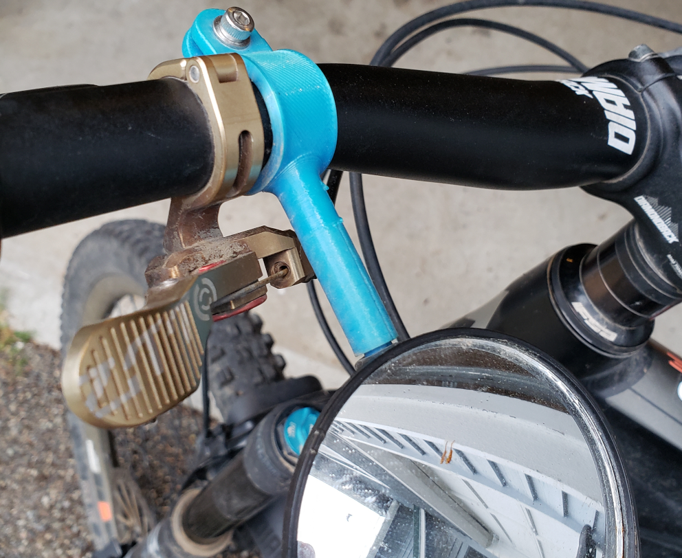
Figure 1: My custom bike mirror mountLook at Figure 1 at the right — see the blue plastic cylinder between the handlebars and the mirror? That's my custom bike mirror mount. My bike mirror came with a fragile mount that broke when I first rode in rough terrain (a perfectly good mirror with a crappy mount). So, using SolveSpace and the methods described in this article, I made a custom mount and printed it with flexible plastic on my 3D printer. Problem solved!
Definitions
Designing with a computer is called "Computer Aided Design" or CAD. The 3D printing phase is called "Computer Aided Manufacturing" or CAM. In shorthand that's CAD/CAM.
As time passes CAD/CAM is becoming more important as well as easier and less expensive. Did you know NASA installed a 3D printer at the International Space Station? They realized it would be simpler and more efficient to design and print new and replacement parts right at the space station than wait for the astronauts to tell Houston they've had a problem.
Many CAD programs are expensive to buy or access, but there are some free and open-source CAD programs too. For this article I decided to focus on SolveSpace, which is free, open-source and easy to use.
First, install the SolveSpace program, which is free and available at this Webpage for Windows, Macintosh and Linux.
Before showing a detailed description, here are links to some useful resources:
Arachnoid.com:
SolveSpace.com:
- solvespace.com — primary site index.
- SolveSpace Documentation — entry point for all documentation.
- SolveSpace Tutorials — most of these tutorials are advanced, perhaps not suitable for those without prior CAD program experience.
- SolveSpace Reference Manual — not end-user friendly, but complete.
- SolveSpace Interface Library Documentation — this documents the SolveSpace interface library, with allows access to the core SolveSpace engine without the user interface.
- SolveSpace menus and keyboard shortcuts (PDF download)
First Steps

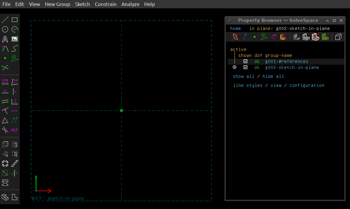
Figure 2: SolveSpace user interface
(click for full-size)NOTE: If you prefer videos to text instruction, see the section "Released Videos" at the top of this page.
When you first run SolveSpace you're presented with a two-dimensional sketch plane embedded in a three-dimensional space (Figure 2). The default plane is XY, which can be thought of as a flat two-dimensional surface like a table top or paper sketch pad. In this coordinate system the X dimension is left/right and Y is far/near.
Figure 3: Cartesian three-dimensional space
(click to play)Even though a SolveSpace sketch is confined to two dimensions, when processing your sketch SolveSpace works in three dimensions and can create solid objects. The video in Figure 3 shows the three Cartesian dimensions with the same colors SolveSpace uses:
- Red for X (left/right)
- Green for Y (far/near)
- Blue for Z (up/down)
The SolveSpace sketch editor shows three small arrows (a bit like the video in Figure 2) at the lower left to help with orientation.
It's important to know which SolveSpace spatial plane you're sketching in, especially if you plan to 3D print what you create. In that case you will want to give a created object the most favorable orientation for the 3D printer environment. But for now, the default XY plane is fine.
This is a walk-through of activity phases from first rough sketch to a complete CAD model suitable for 3D printing or use in a computer graphics project.
Remember Figure 1 above, my bike mirror project? Let's make that our example. Here are the phases for such a project using SolveSpace:
Phase 1: Sketch in 2D

Figure 4: Sketch user interface (click for full-size)
In this phase, the user creates some two-dimensional sketches of the desired object. The lines and curves in the sketch must be fully described — each line has a length and position, each curve has an arc length, and so forth. This description process is called "constraining". Figure 4 shows a "fully constrained" sketch — all the drawing elements and their relationships are described without ambiguity.
It's important to understand the constraint process, without which a project cannot go forward. An underconstrained sketch isn't described clearly enough, but one may also have an overconstrained sketch, where a sketch element is described in more than one way such that a conflict arises.
Both underconstrained and overconstrained sketches must be corrected for a project to move forward. The constraint resolution process is likely the most difficult CAD aspect for beginners, and requires some time and study to get right.
Phase 2: Extrude in 3D

Figure 5: Solid Extrusion in 3D (click for full-size)
In Figure 5 the sketch has been rotated in three dimensions to create a solid object.
Rotation is just one of many options for converting a 2D sketch into a 3D object. Other options are linear extrusion, "step and repeat" duplication by either rotation or translation, and a combined rotation/translation option that creates a helix, useful for creating machine threads.
Phase 3: Export Results

Figure 6: Complete Project ready for export
(click for full-size)Figure 6 shows the project immediately prior to export. The final form consists of multiple sketches, each extruded in 3D in different ways to create the desired form, and combined into a single result.
SolveSpace has a number of export options — file types suitable for 3D printing or interfacing with other CAD/CAM programs. In most cases the best export choice for 3D printing is "File .. Export Triangle Mesh", which creates what is normally called an STL (stereolithography) file. Most 3D printing slicer programs accept this file type, and graphics programs like Blender also accept this format.
Phase 4: View in 3D

Figure 7: Bike mount and another project
as seen by Blender (click for full-size)This is an optional but desirable project phase. Figure 7 shows the bike mirror mount project, and another project result (threaded hardware), shown in Blender. This option is useful for discovering size conflicts in parts that must work together, like models of threaded bolts and nuts. I use this preview method to detect and correct dimensional conflicts before 3D printing and other uses.
I always preview my projects in Blender. I have the excuse that I can detect some kinds of errors before 3D printing, but in truth, I do this because my CAD/CAM projects always look better in Blender than in reality.
Phase 5: Process in a 3D printing slicer program (Prusa Slicer)

Figure 8: As shown by PrusaSlicer (click for full-size)
Figure 8 shows the mirror mount STL file imported into a 3D print slicer program in advance of printing. In this phase the user chooses the right kind of print filament, selects the appropriate hot end and print bed temperatures and other settings for a given kind of printing filament. The bike mirror mount project uses TPU filament, which creates a flexible part able to be wrapped around the bicycle handlebars.
Phase 6: Print in 3D

Figure 9: As 3D printed (click for full-size)
Figure 9 shows the 3D printed bike mirror mount, after all the prior steps: creation in SolveSpace, export from SolveSpace as an STL file, processing in a 3D slicer program and finally printing on an FDM (Fused Deposition Modeling) printer using flexible filament (TPU).
Figure 1, at the top of this article, shows the 3D printed bike mirror mount in service.
Summary
This article section only provides an overview of a typical SolveSpace project without many details. To learn SolveSpace I recommend immersion in a test project where any number of mistakes and restarts are acceptable, accompanied by reading the published SolveSpace documentation.Remember, this article is intended to serve as a resource archive for my YouTube videos about SolveSpace and related topics.
Here is an interactive view of the SolveSpace user interface with most of the controls commented — hover over controls to see their description:
Click Here, or click the image below, for a larger view.
Here is a list of SolveSpace project files from my rather large collection, useful as examples and for practice. If you reuse/release all or part of them, simply acknowledge the author as required by the GPL license: "© Copyright 2023, P. Lutus".
- 3D calibration test cube — a classic 3D printer calibration aid, 20mm per side, with printed labels showing the cardinal dimensions X, Y and Z. For the labels, users will need to specify a locally available TrueType font, which for licensing reasons is not included in the source file.
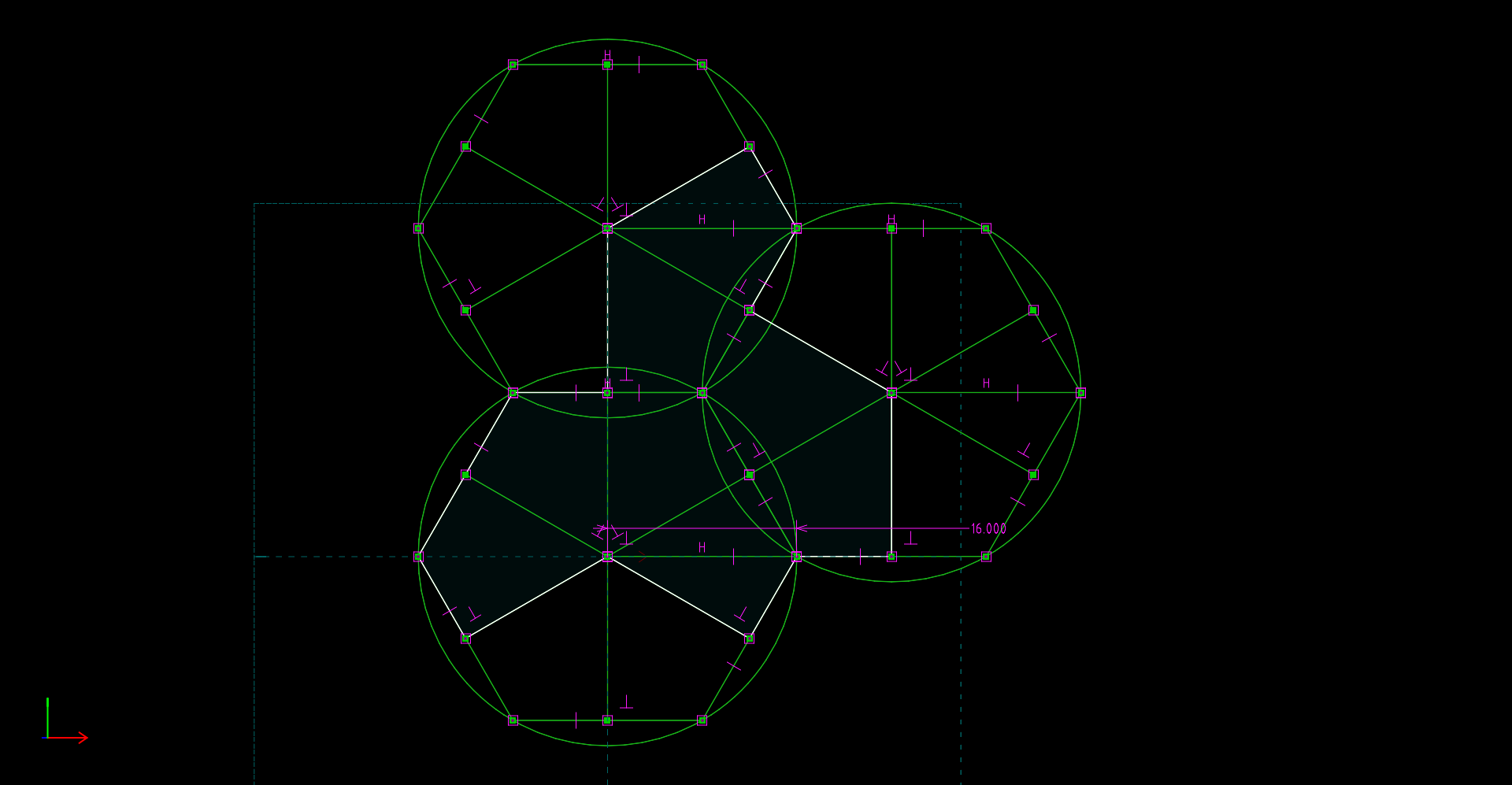
- Aperiodic Tile version 1 — This is a printable aperiodic tile as explained in this Scientific American article. Unlike Spectre below, this aperiodic tile version requires that the tile's mirror image be used at times. In this SolveSpace design, three hexagons are constructed, then the perimeter of the tile is created using coordinates provided by the hexagons. Click here for an image of the key sketch. Notice that the majority of the lines are construction lines, meaning lines that provide dimensioning/geometry but don't become part of the exported sketch.
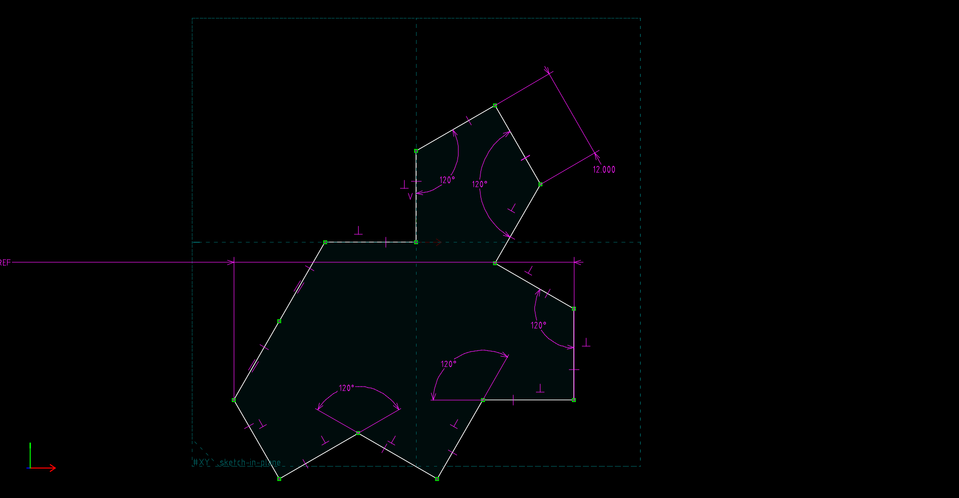
- Aperiodic Tile version 2, i.e. Spectre — this aperiodic tile model does away with the requirement for a mirror image of the pattern. Many have argued that this is the only true aperiodic tile design. See An aperiodic monotile for a full explanation. Click here for an image of the key sketch.
- Bike mirror mount. This is the flexible mirror mount fully described above.
- Cup, 400ml. This is a relatively simple, useful cup design that shows a few intermediate to advanced methods to accomplish its design. Like the calibration cube listed above, because of a capacity label printed at the bottom of the cup, this project also requires specifying a locally available TrueType font.
- Cup, Advanced Design, 400ml. This is more practical cup that goes beyond a simple tutorial design.
- Metric M10 size threaded bolt. This design creates a working, practical Metric bolt. It uses the SolveSpace helix feature and some careful dimensioning to make a practical bolt correctly sized to thread with a 3D printed nut (see below) or a metal nut of the same size.
- Metric M10 size nut. This project correctly interacts with the bolt listed above, or with metal hardware of the same size.
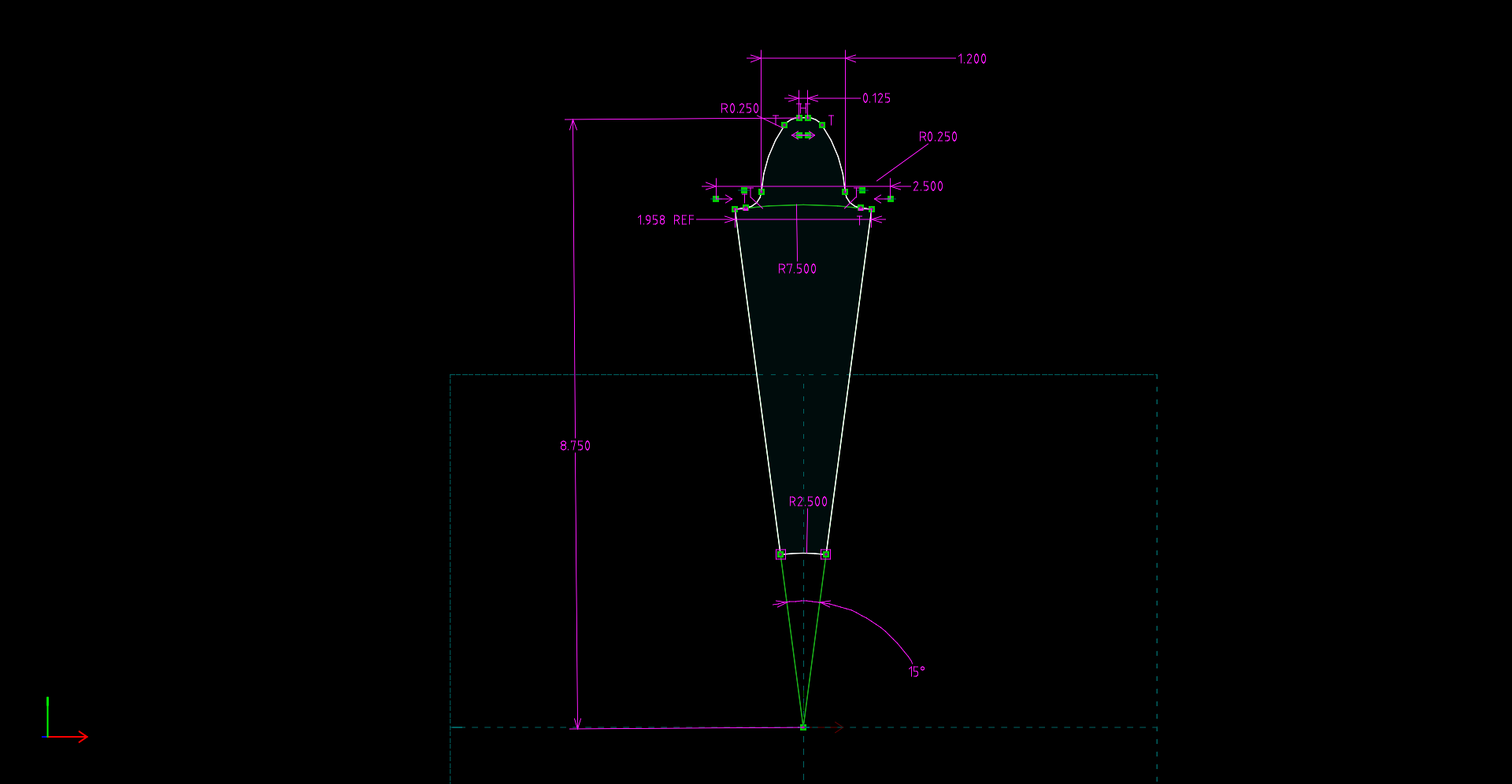
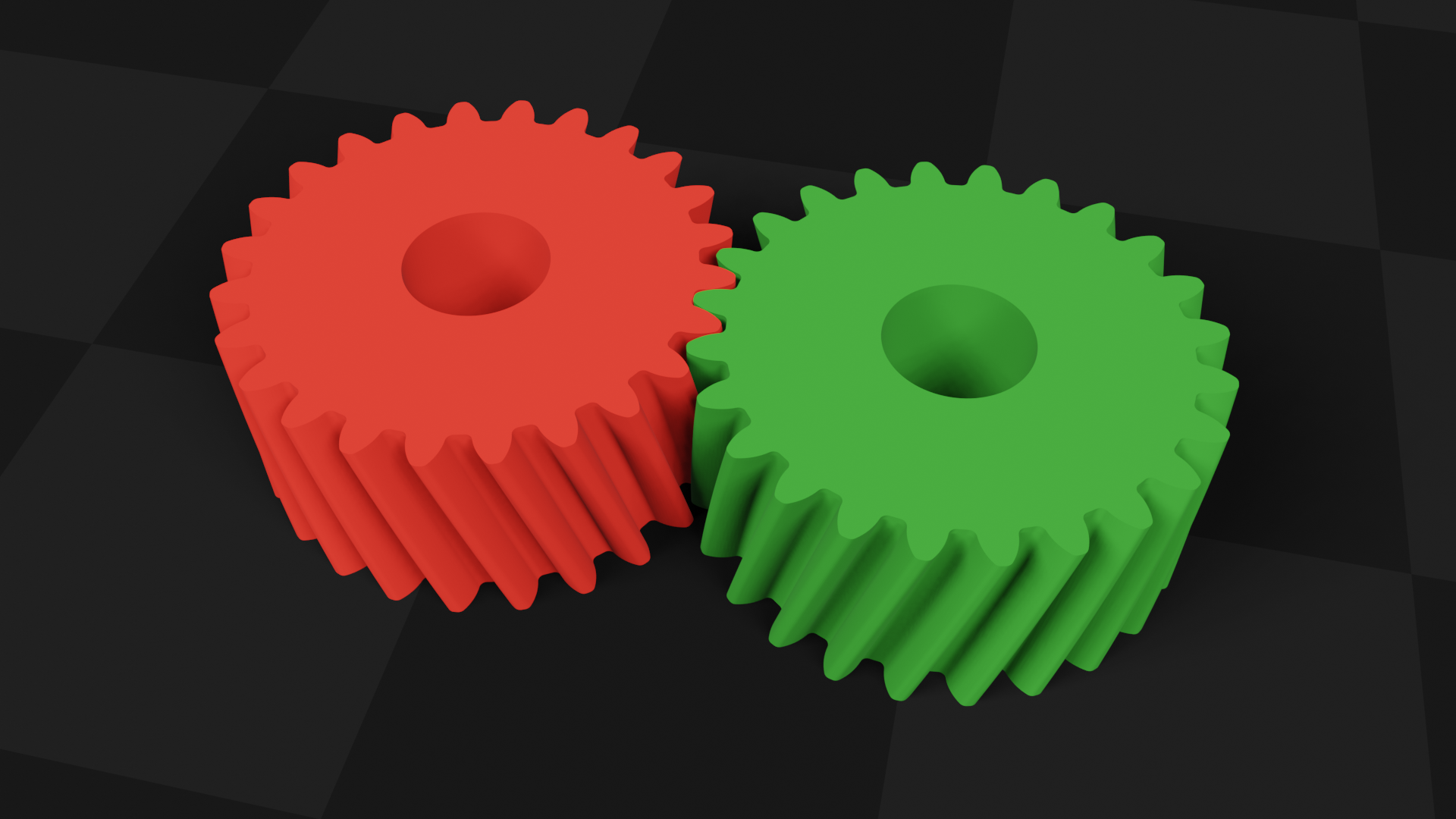
- Helical Gear. An exercise in advanced gear design. Click here to see the primary sketch. Click here to see a Blender view of the meshed gears.
- Click here to download a ZIP archive containing resources related to my second SolveSpace tutorial video.
As explained above this article is meant to support my CAD/CAM / SolveSpace videos. Most such videos try to stand alone without any technical resources, but that's not a realistic strategy, especially for students. This article is a work in progress — visit again to see more content.
| Home | | Computer Graphics | | Computer Aided Design | | Share This Page |