Share This Page
| Home | | Hardware | | Share This Page |
 USB Power Issues
How to reliably power your USB peripherals
— Copyright © 2013, P. Lutus — Message Page —
(double-click any word to see its definition)
Recently I've been rewriting SSHelper, one of my Android applications, using a Nexus 7 as a test device. In the middle of my development effort, Google released a version of Jelly Bean 4.3 for the Nexus 7, which was automatically installed on my device as I worked.
I didn't think much about the upgrade. Such things normally happen without anyone noticing, except possibly those who need a new included feature. But within about eight hours of the upgrade my Android device shut itself down, battery essentially dead, even though it was connected to a USB hub and therefore presumably getting power.
I went online and read that newer Android releases seemed to be requiring more power from the device's battery, which sometimes cause shorter hours of operation when away from a power source. But my device was connected to power (the USB hub), so (at least in principle) it wasn't relying on its battery. I realized that I had never before seen an Android device shut itself down while connected to power. I was momentarily mystified.
Then I began to think about something that happened a few months ago, something I realized might be related. At that time I began to see error reports from a USB-connected hard drive, a drive that eventually failed entirely. At the time I thought it might have been a simple case of a bad drive, even thought the drive was relatively new. I began to think I was seeing power issues, and I decided it was time to look into how USB hubs provide power.
USB host connectors () perform two functions:
- They provide a signal pathway for data to/from the peripheral.
- The provide some power to the peripheral.
How much power? Online sources differ (surprising no one), but under USB 2.0, today's most commonly applicable standard, it's 500 milliamperes (1/2 ampere). This means that, if a peripheral needs 500 milliamps, the source must provide it (to me that sounds like the traditional definition of "home" — if you have to go there, they have to take you in).
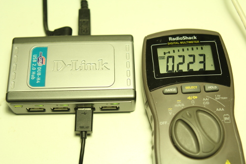
But, being naturally skeptical (the single most important trait in a scientist) and having just seen my Nexus 7 turn itself off while connected, I decided to see if D-Link, the supplier of my USB 2.0 hubs, was meeting the USB 2.0 specification. Here's the result:
Figure 1: D-Link DUB-H4 USB 2.0 hub short-circuit currentOkay, let's be perfectly clear. This D-Link hub, model DUB-H4 (not the A revision available at the time of writing, but an older design), of which I have about eight scattered about, is clearly marked as being USB 2.0 compliant. But as the above picture shows, with only one "device" attached (a current meter) and while powered by an adaptor able to provide 2.5 amperes, the hub can only deliver 223 milliamperes into a short circuit, or 45% of the current required by USB 2.0.
This was now a crisis. I needed to continue working and finish upgrading my Android program SSHelper. For this, I needed to stay connected to a USB hub (which serves the purpose of downloading code and uploading debugging messages), but I also needed the device to charge its battery and not go offline unexpectedly. The next section explains how I solved the problem.
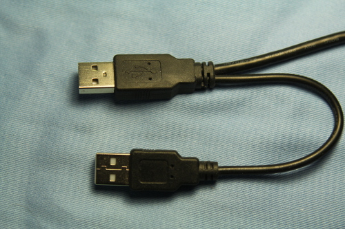
I have some special cables that typically come with USB hard drives. The host end looks like this:
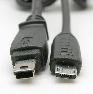
Figure 2: Special USB hard drive cableFigure 3: Mini-USB (left, micro-USB (right)Whan I first saw this cable, I realized it was meant to double the power available to the USB drive, at the expense of halving the number of connections available on a USB hub. But I thought, "Well, if it's connected to a compliant USB 2.0 hub like mine, it will get 500 milliamps, more than this drive needs." So I didn't sacrifice my precious hub connections and only attached the data + power connector (top of Figure 2) to the hub. And that, boys and girls, is how I lost my USB drive — it struggled to operate on less than 1/2 the current specified by USB 2.0, and it eventually died.
But back to the present. Could I use this special cable to double the current available to my Nexus 7? Well, no, becuse the other end of the cable in Figure 2 has a mini-USB connector, and the Nexus 7 uses a micro-USB connector (figure 3).
The problem: I wanted to continue working, and I didn't have a USB hub that could keep my Android device alive by itself, so I needed a special cable immediately. My solution was to splice two USB cables together. The operation is relatively simple for one with a bit of electronic skill:
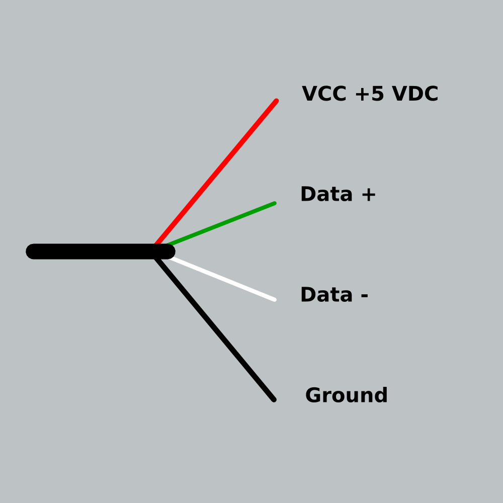
- The wires in most USB cables are color-coded (figure 4):
- Red: +5 volts
- Black: power ground
- Green and White: Data
Figure 4: USB cable color code- Select two USB cables you're willing to sacrifice. One of the cables will be tapping power from an independent source to power your peripheral (call this the power cable), and the other will deliver power and data to your peripheral, so it needs to have the right kind of peripheral connector (see figure 3 above) (call this the data cable).
- Prepare the data cable (the cable that connects the peripheral to the hub):
- Using a sharp knife and some care, cut the outer covering of the data cable lengthwise about four inches (10 centimeters), without cutting the wires inside.
- Separate the inner wires and shield (if present) from the covering layer.
- Carefully separate the shielding and the color-coded wires inside.
- Now cut the shield and the red and black wires, but don't cut the green and white wires.
- Prepare both ends of the shield and red and black wires for connection — strip away a small distance (roughly 3/8 inch or 1 centimeter) along the insulation of each end of the red and black wires.
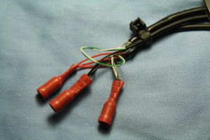
Figure 5: Spliced USB cables- Prepare the power cable (the cable that will connect to a separate power source):
- Snip off the end of this cable near the peripheral end (to povide adequate length for connecting to power soures) and discard the peripheral connector.
- Open up the end of this cable and separate the wires. You won't be using the data wires (green and white) on this cable, so they can be cut off to keep them out of the way.
- Prepare the remaining wires (the shield, red and black wires) for connection as above — strip away some insulation from the red and black wires.
- Connect the power and data cables — connect red to red, black to black, shield to shield. Use whatever connection method you prefer — solder, wire nuts, crimp connectors, whatever.
- Refer to figure 5 and remember that each of the above connections has three wires — for example, two red wires from the two ends of the data cable, and a third red wire from the power cable.
- Remember also that you shouldn't have cut the green and white wires on the data cable — they should be left as they were originally, as shown in figure 5.
- Note the cable tie in figure 5 that binds the three cable ends together (upper right). This is meant to relieve the strain on the fragile connections which, if not somehow protected from strain, will quickly give way.
Figure 6: Wiring diagram.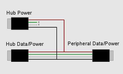
Here's the result of the above project (note that the power and data cables are connected to the same hub):
Figure 7: Current measurement for two parallel connections.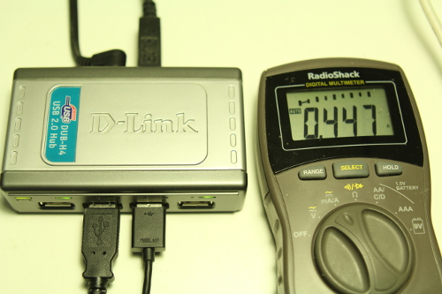
Notice that, even with two cables drawing power in parallel from the D-Link hub, it still won't provide the USB 2.0 specified current of 500 milliamperes.
I've spent some time reading about this issue online. Some people think a USB hub will deliver the full power available from its power adaptor, divided among the connected loads, so all available power would be delivered to one connected device, two connected devices each would get 1/2 of available power, etc.. That may be true for some hubs, but a compliant hub needs to be able to tolerate a short circuit, and during a short circuit the device has to dissipate all the power as heat (that's 2.5 watts per connector for a compliant hub).
This argues that a simpler and wiser design would present the same current limit on each connector, regardless of the power source's available current. That's true in this case — the D-Link hub I used in these tests was connected to a power adaptor able to deliver 2.5 amperes, but the pictures show an absolute limit of less than 1/4 ampere per connector. My point here is that the D-Link designers made the right choice by limiting current to the same level at each connector regardless of the number of connections, but they chose the wrong current.
For the case of connecting two completely unrelated power sources together in this scheme, one might be concerned that a voltage mismatch might destroy some electronics. But because of the way these kinds of circuits work, this isn't a likely outcome for two power sources each meant to deliver five volts.
While preparing this article I tested all my USB power sources — small plug-in adaptors with a USB connector on top, 12 volt adaptors meant to plug into a cigarette lighter socket, and so forth. All of them delivered one ampere or more, without exception. At least at my house, the problem that led to this article is limited to the D-Link hubs, each of which I have connected to a power adaptor able to deliver more than two amps. I should say that my D-Link hubs are more than five years old, and there is a new product (D-Link DUB-H4 revision A) with the same model number. For all I know the new hubs don't have this problem. I would appreciate hearing from anyone who has the new D-Link hub and a multimeter, and who is willing to make the short-circuit test I show above.
Parenthetically, the above Amazon.com link to the new product has quite a number of negative reviews. I hope no one thinks I'm promoting this product by linking to the Amazon.com site. My opinion is that there are better choices out there at competitive prices.
| Home | | Hardware | | Share This Page |